Blog
Micro Switches: Working Principle, Key Parameters & Practical OEM Selection Guide

(H1)
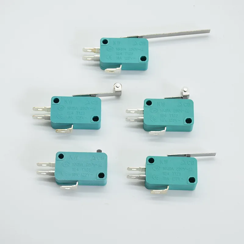
Micro switches are widely‑used mechanical snap‑action switches, also known as limit switches. They feature fast response, compact size and long mechanical life. They are commonly seen in household appliances, industrial equipment, medical devices and automotive accessories. This guide explains micro‑switch basics, core parameters and practical selection tips for OEM buyers and engineers.
How Does a Micro Switch Work (H2)
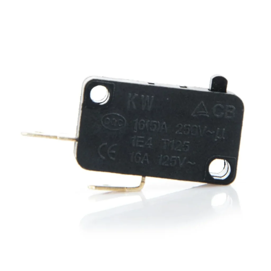
A micro‑switch relies on internal spring‑driven snap‑action mechanism. When external force presses the actuator, the internal metal contacts switch rapidly between ON and OFF status. Once the pressure is removed, the switch returns to its original position automatically.
This snap‑action design ensures fast, stable contact switching, independent of the speed of pressing force.
Main Micro‑Switch Types By Actuator (H3)
‑Basic push‑button type: direct‑press structure, simple and compact.
‑Lever type: with metal lever, used for position detection and limit triggering.
‑Roller lever type: equipped with roller, suitable for mechanical stroke triggering.
‑Hinge lever type: widely used for door‑sensor and position‑detect scenarios.
Critical Parameters For Micro‑Switch Selection (H2)
Wrong parameter selection is the main cause of early‑stage failure in finished products.
Electrical Rating (H3)
‑Rated voltage & rated current: AC and DC ratings are different. Do not exceed the maximum current and voltage.
‑Resistive load is the standard reference; inductive or lamp load will shorten service life.
Mechanical Life & Electrical Life (H3)
‑Mechanical life: switch cycles without electric load, can reach millions of times.
‑Electrical life: actual working cycles under rated current, always shorter than mechanical life.
‑For high‑frequency‑trigger end products, give priority to higher electrical‑life models.
Actuator Force & Travel (H3)
‑Operating force: the force needed to trigger the switch. Too heavy or too light will affect user experience.
‑Total travel: movement distance of actuator. Match your mechanical structure design.
Environmental Performance (H3)
‑Normal models are for indoor dry environment.
‑Waterproof / dust‑proof micro‑switches are required for humid, dusty equipment.
Common Application Scenarios (H2)
‑Home appliances: microwave door detection, water heater safety interlock, oven limit sensing.
‑Industrial equipment: mechanical limit position detection, safety protection trigger.
‑Automotive accessories: car‑door sensing, window limit detection.
‑Consumer electronics: equipment door‑open safety interlock.
Typical Micro‑Switch Failures & Causes (H2)
‑Poor contact / intermittent switching: contact oxidation, dust pollution, current overload.
‑No trigger response: spring fatigue, actuator mechanical damage.
‑Short service life: electrical life is underestimated for real‑world load.
Note: When contact failure occurs, do not continue to use the faulty micro‑switch, risk of overheating exists. Replace it directly.
OEM Procurement Suggestions (H2)
1. Clarify real‑world load type: resistive, inductive or lamp load. Do not only refer to mechanical‑life data.
2. Confirm required actuator style, operating force and travel to match your mechanical assembly.
3. For harsh‑condition applications, choose IP rated waterproof or dust‑proof versions.
4. Run sample aging test before mass order, verify contact stability under real working conditions.
Conclusion (H2)
Micro‑switches are simple‑structure but critical safety components. Pay attention to electrical rating, electrical life and mechanical parameters. Proper selection can greatly improve finished‑product stability and reduce after‑sales failure rate.